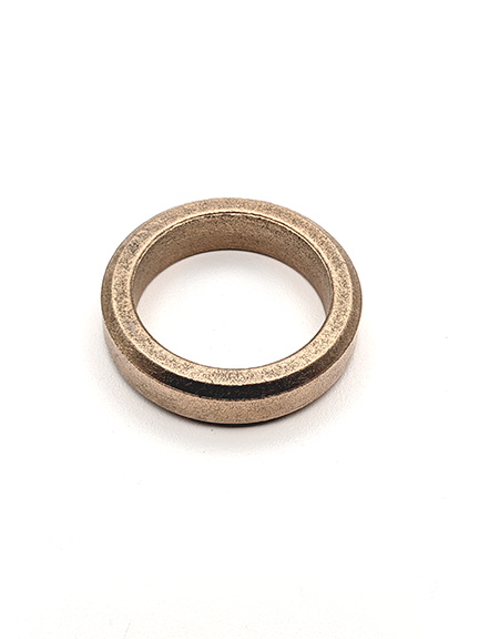
Understanding Compression Limiters in product manufacturing
Compression limiters are engineered inserts used in product manufacturing to protect plastic, composite, or soft-material assemblies from being crushed when a screw, bolt, rivet, or clamp is tightened. They create a controlled load path through a stronger component, so the joint can be tightened securely without deforming the surrounding material. In practical terms, they help manufacturers build lighter products with reliable fastening performance and fewer failures caused by over-compression.
What are compression limiters?
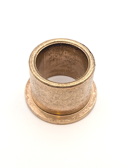
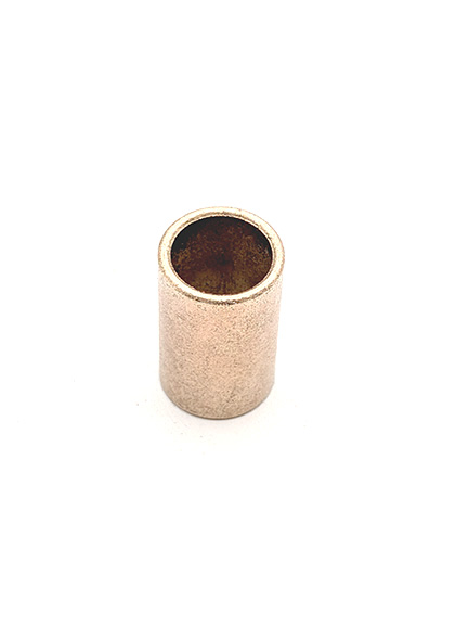
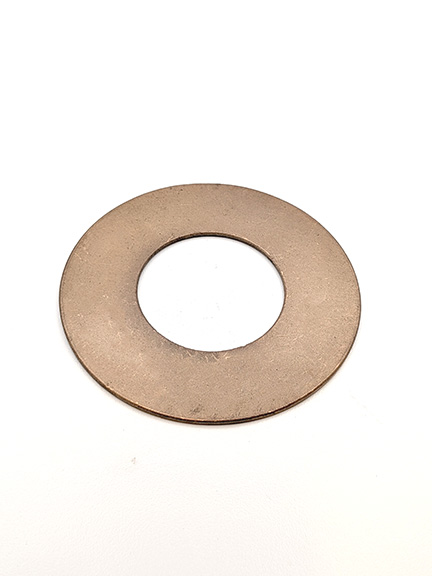
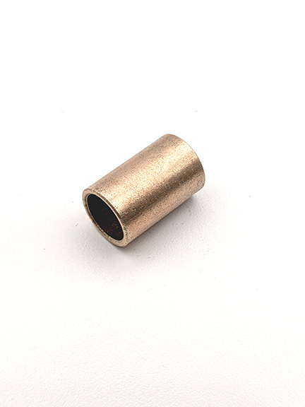
Compression limiters are small mechanical components, often shaped like sleeves, tubes, collars, or bushings, that sit inside or around a fastener hole. When the fastener is tightened, the limiter takes the compressive force instead of allowing the parent material to collapse. This is especially important when metal fasteners are used with plastics, rubber, molded composites, or other materials that may creep, crack, or deform under sustained load.
A compression limiter does not usually provide the fastening force by itself. Instead, it works as part of a joint system that may include a screw, bolt, washer, insert, gasket, housing, or mating bracket. Its purpose is to maintain clamp load while preserving the shape and function of the manufactured part.
Core characteristics of compression limiters
A well-designed compression limiter is simple, but it solves several engineering problems at once. Its exact form depends on the product, material, installation method, and required fastening strength.
Key characteristics include:
- Load-bearing function: It carries the compressive force generated by the tightened fastener.
- Material compatibility: It is selected to work with the surrounding plastic, elastomer, composite, or molded part.
- Dimensional control: Its length, inner diameter, outer diameter, and wall thickness influence joint performance.
- Installation fit: It may be molded in place, pressed in, heat-staked, ultrasonically inserted, or assembled during final build.
- Resistance to creep: It helps reduce long-term deformation in materials that relax under pressure.
- Repeatable assembly: It gives operators or automated equipment a more predictable tightening condition.
These details matter because fastening failures are rarely caused by one factor alone. A joint may pass an initial inspection but loosen later if the base material slowly compresses, the limiter is too short, or the torque setting does not match the assembly design.
How do compression limiters work in a manufactured product?
Compression limiters work by redirecting clamp force through a rigid, controlled path. When a screw or bolt is tightened, the fastener head and mating surface apply pressure to the joint. Without a limiter, that pressure can squeeze the surrounding plastic or softer substrate until it distorts, cracks, or loses the intended clamp load.
With a limiter in place, the fastener clamps against the limiter rather than only against the softer component. The limiter acts like a structural spacer, stopping the material from being compressed beyond its intended limit. This allows the fastener to be tightened enough to hold the assembly together while preventing damage to the part.
For example, a plastic housing attached to a metal frame may need strong fastening for vibration resistance. If the screw is tightened directly against the plastic, the housing may deform or creep. If a properly sized compression limiter is installed in the boss or hole, the screw load transfers through the limiter and into the frame, improving joint durability.
Compression limiters in overmolding (and the role of overmolders)
Compression limiters are frequently paired with overmolding, a process used to combine metal and plastic into a single integrated component. In a typical overmolded assembly, a metal insert (which may be a stamped bracket, machined bushing, or formed tube) is placed into an injection mold and then plastic is molded around it. The plastic becomes the outer geometry, while the metal provides localized strength, threads, wear resistance, or load-bearing capability.
Overmolding is sometimes described alongside insert molding. The terminology varies by industry and supplier, but the functional idea is the same: the metal component is present during molding so the plastic encapsulates it and creates a bonded or mechanically locked interface.
An overmolder is the manufacturer (often a contract injection molder) that specializes in producing these hybrid parts. Overmolders typically control the insert-handling method (manual loading, automation, fixturing, and inspection) and the molding parameters needed to prevent insert movement, voids, or flash that would affect the final dimensions of the fastener location.
In this context, a compression limiter can be:
- Molded in place as the insert itself: A metal sleeve compression limiter is loaded into the tool and overmolded so it becomes permanently located within a plastic boss.
- Co-molded with additional metal features: The limiter may be integrated into a larger metal insert that also includes brackets, grounding points, or alignment features.
- Added after molding: In some designs the overmolded plastic includes a bore or pocket that receives a press-fit or heat-inserted limiter later in assembly.
Combining metal and plastic through overmolding changes the joint design space. It can improve load transfer and assembly repeatability, but it introduces engineering constraints that are directly relevant to compression limiters, including:
- Retention and anti-rotation: Limiter inserts may use knurls, grooves, undercuts, or head features so the plastic mechanically locks to the metal and prevents spin during tightening.
- Thermal expansion mismatch: Metal and plastic expand at different rates, so the interface must tolerate temperature cycling without creating looseness, cracking, or stress concentration at the boss.
- Tolerance stack-up: Insert location in the mold, plastic shrink, and post-mold warpage can affect the limiter’s effective length relative to mating surfaces, which directly affects clamp load.
- Surface and corrosion considerations: Plating, passivation, or material choice may be used to manage corrosion, especially when the overmolded part is used outdoors, in automotive environments, or near dissimilar metals.
When an overmolded part is intended to be fastened repeatedly (service access, repair, or modular subassemblies), integrating a compression limiter can be a practical way to protect the plastic structure while still allowing higher, more consistent tightening torque.
Where compression limiters are commonly used
Compression limiters are useful wherever a strong fastener must pass through a weaker or more flexible material. They are common in products that combine molded parts with metal hardware, especially when the assembly must survive handling, vibration, heat, or repeated service.
Practical examples include:
- Automotive components: Plastic covers, housings, brackets, interior trim, battery enclosures, and under-hood assemblies.
- Consumer products: Appliance housings, power tool casings, electronic enclosures, and durable molded parts.
- Industrial equipment: Control boxes, protective covers, machine guards, and composite panels.
- Medical and laboratory devices: Molded housings that require stable fastening without cracking sensitive components.
- Outdoor products: Assemblies exposed to temperature changes, moisture, or repeated mechanical stress.
In each case, the limiter helps balance two goals that often conflict: using lightweight or moldable materials while still achieving dependable mechanical fastening.
Compression limiters and material behavior
Many product failures begin with a mismatch between fastener force and material behavior. Plastics and composites can be strong, but they do not always respond like metal under clamp load. Some materials creep over time, meaning they slowly deform under constant pressure. Others may crack if the fastener load is concentrated in a small area.
A compression limiter gives the designer more control over that behavior. It can help maintain spacing between components, reduce stress around the fastener hole, and protect molded bosses from crushing. However, the limiter must be correctly specified. If it is too long, the joint may not clamp the part properly. If it is too short, the surrounding material may still be compressed. If the inner diameter is wrong, the fastener may bind, shift, or fail to seat correctly.
This is why compression limiters are best considered during product design, not added as an afterthought. The surrounding wall thickness, boss geometry, assembly torque, washer choice, and mating surface all affect whether the joint performs as intended.
How are they different from compression and limiting in audio?
In manufacturing, compression limiters are physical components used to prevent mechanical over-compression. They should not be confused with audio tools such as dynamic range control, compressors, or limiter plugins. Those terms describe signal processing methods that manage loudness, peaks, and level variation in sound production.
The shared word “limiter” can create confusion, but the concepts are different. A manufacturing compression limiter controls mechanical load in a fastened assembly. Audio limiter plugins control signal peaks in a digital or analog audio chain. Dynamic range control changes the relationship between quiet and loud sounds, while a physical compression limiter changes how tightening force moves through a product.
The practical takeaway is simple: in product manufacturing, the term refers to hardware and joint protection, not sound processing.
Common design considerations
Choosing a compression limiter involves more than selecting a sleeve that fits the hole. The component must match the product’s performance needs and manufacturing process. A designer may need to consider assembly torque, vibration exposure, thermal expansion, part tolerances, corrosion conditions, and whether the limiter will be installed before or after molding.
A basic selection checklist includes:
- Identify the parent material. Determine whether the surrounding part is plastic, rubber, composite, or another compressible material.
- Define the fastener load. Estimate the tightening force and service loads the joint must withstand.
- Match the limiter length. Ensure the limiter supports the joint without preventing proper clamping.
- Check hole and boss geometry. Confirm that the part has enough material around the limiter to resist splitting or pullout.
- Plan the installation method. Decide whether the limiter will be molded in, pressed in, heat inserted, or assembled separately.
- Validate through testing. Confirm that the joint maintains clamp load and avoids deformation under real use conditions.
This checklist does not replace engineering validation, but it helps frame the decisions that affect reliability.
Common misconceptions
Compression limiters are sometimes treated as generic spacers, but that can lead to poor joint performance. They are load-control components, and their dimensions and placement matter.
Common misconceptions include:
- “Any metal tube will work.” The limiter must be sized for the fastener, material, and torque condition.
- “More tightening is always better.” Excessive torque can still damage the assembly or surrounding features.
- “The limiter fixes weak design.” It improves load transfer, but it cannot compensate for inadequate wall thickness or poor boss design.
- “It is only needed for high-load parts.” Even moderate clamp loads can cause creep or distortion in softer materials.
Understanding these limits helps teams use compression limiters as part of a complete fastening strategy rather than a quick fix.
Why compression limiters matter
Compression limiters matter because they protect product quality at the point where many assemblies are most vulnerable: the fastened joint. They allow manufacturers to combine lightweight molded parts with strong mechanical fasteners while reducing the risk of cracking, crushing, loosening, and long-term deformation.
For designers, they offer better control over clamp load and material behavior. For production teams, they can support more repeatable assembly. For end users, they help products stay intact, aligned, and functional through normal use. When specified correctly, a small compression limiter can make a significant difference in the durability of the finished product.